Resin material handling instructions
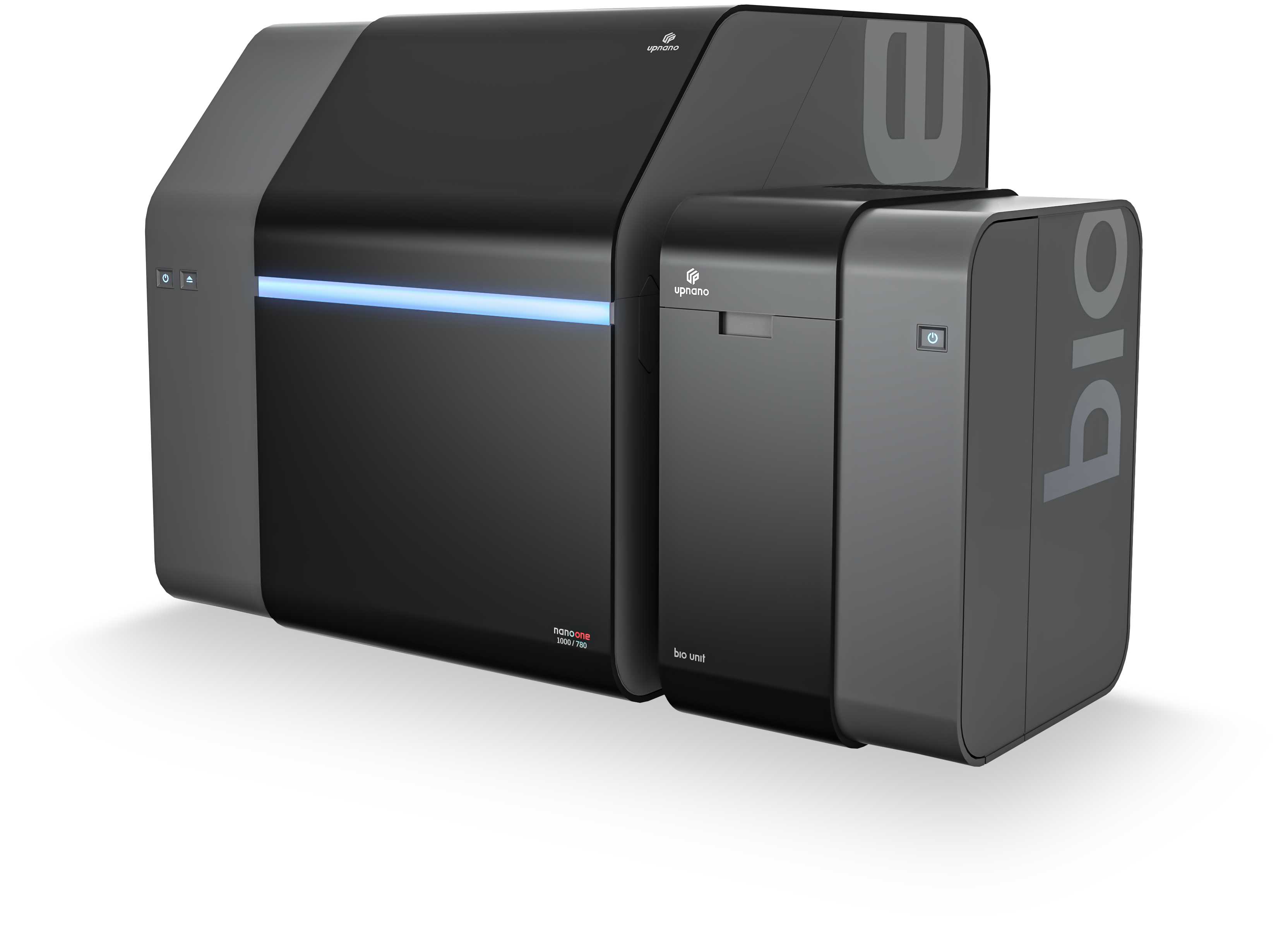
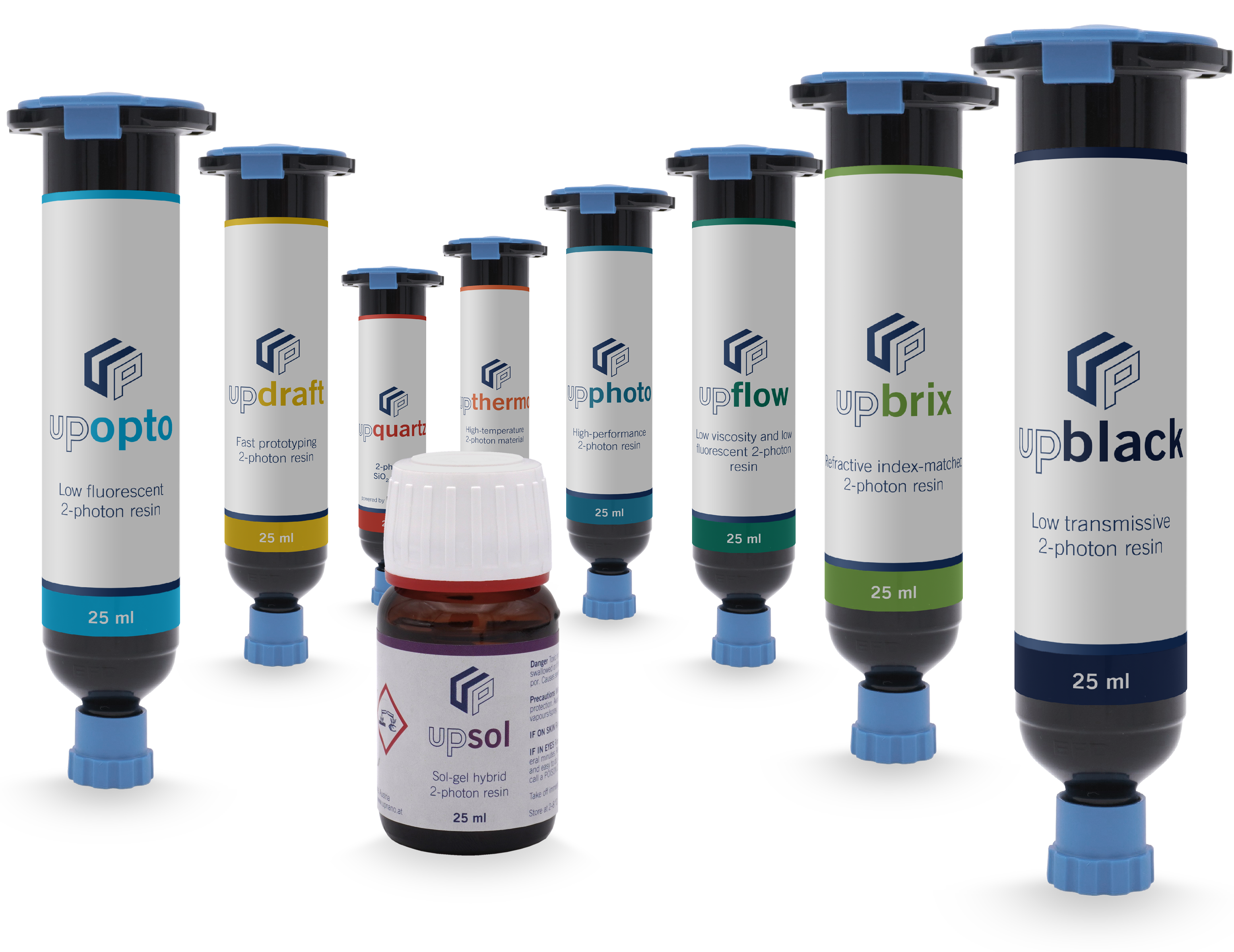
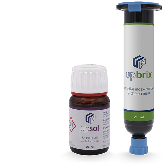
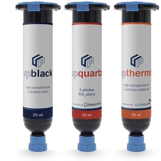
UpNano offers a portfolio of high-performance 2-photon resins optimized to fully exploit the capabilities of ultrafast high-resolution printing systems like the NanoOne. With nine resins tailored for specific applications, ranging from performance photopolymers to optically transparent materials for optical and microfluidic applications, to biocompatible formulations tested for in-vitro cytotoxicity according to EN ISO 10993-5:2009, these materials provide unmatched versatility and performance. Here you will find specific material handling instructions for each resin.
Comparison of printing capabilities by machine configuration
The following tables provide a detailed comparison of the printing capabilities between the NanoOne 1000 and NanoOne 250 system. The tables outline the resin portfolio available for each system, specifying which objectives and print modes (fine or coarse) should be used with which resin from UpNano’s portfolio. This comprehensive overview helps users identify the optimal machine configuration and resin combination to meet their specific application needs.
Resin portfolio
|
Objectives
|
5x/0.25
|
10x/0.4
|
20x/0.7
|
40x/1.4
|
Print modes
|
||||
|---|---|---|---|---|---|---|---|---|---|
|
Infill mode
|
Fine
|
Coarse
|
Fine
|
Coarse
|
Fine
|
Coarse
|
Fine
|
Coarse
|
|

|
|
|
|
|
|
|
|
|
Vat, bottom-up
|

|
|
|
|
|
|
|
|
|
Vat, bottom-up
|

|
|
|
|
|
|
|
|
|
Vat, bottom-up
|

|
|
|
|
|
|
|
|
|
Vat, bottom-up
|

|
|
|
|
|
|
|
|
|
Vat, bottom-up
|

|
|
|
|
|
|
|
|
|
Vat, bottom-up
|

|
|
|
|
|
|
|
|
|
Heated-vat
|

|
|
|
|
|
|
|
|
|
Vat
|

|
|
|
|
|
|
|
|
|
Top-down, bottom-up
|
- Print set-up possible but not recommended
For detailed information and user guidance, please refer to the material handling sheets.
Resin portfolio
|
Objectives
|
10x/0.4
|
20x/0.7
|
40x/1.4
|
Print modes
|
|||
|---|---|---|---|---|---|---|---|
|
Infill mode
|
Fine
|
Coarse
|
Fine
|
Coarse
|
Fine
|
Coarse
|
|

|
|
|
|
|
|
|
Vat, bottom-up
|

|
|
|
|
|
|
|
Vat, bottom-up
|

|
|
|
|
|
|
|
Vat, bottom-up
|

|
|
|
|
|
|
|
Vat, bottom-up
|

|
|
|
|
|
|
|
Vat, bottom-up
|

|
|
|
|
|
|
|
Vat, bottom-up
|

|
|
|
|
|
|
|
Heated-vat
|

|
|
|
|
|
|
|
Vat
|

|
|
|
|
|
|
|
Top-down, bottom-up
|
- Print set-up possible but not recommended
For detailed information and user guidance, please refer to the material handling sheets.
- UpPhoto
- UpDraft
- UpBrix
- UpOpto
- UpBlack
- UpFlow
- UpThermo
- UpSol
- UpQuartz
UpPhoto
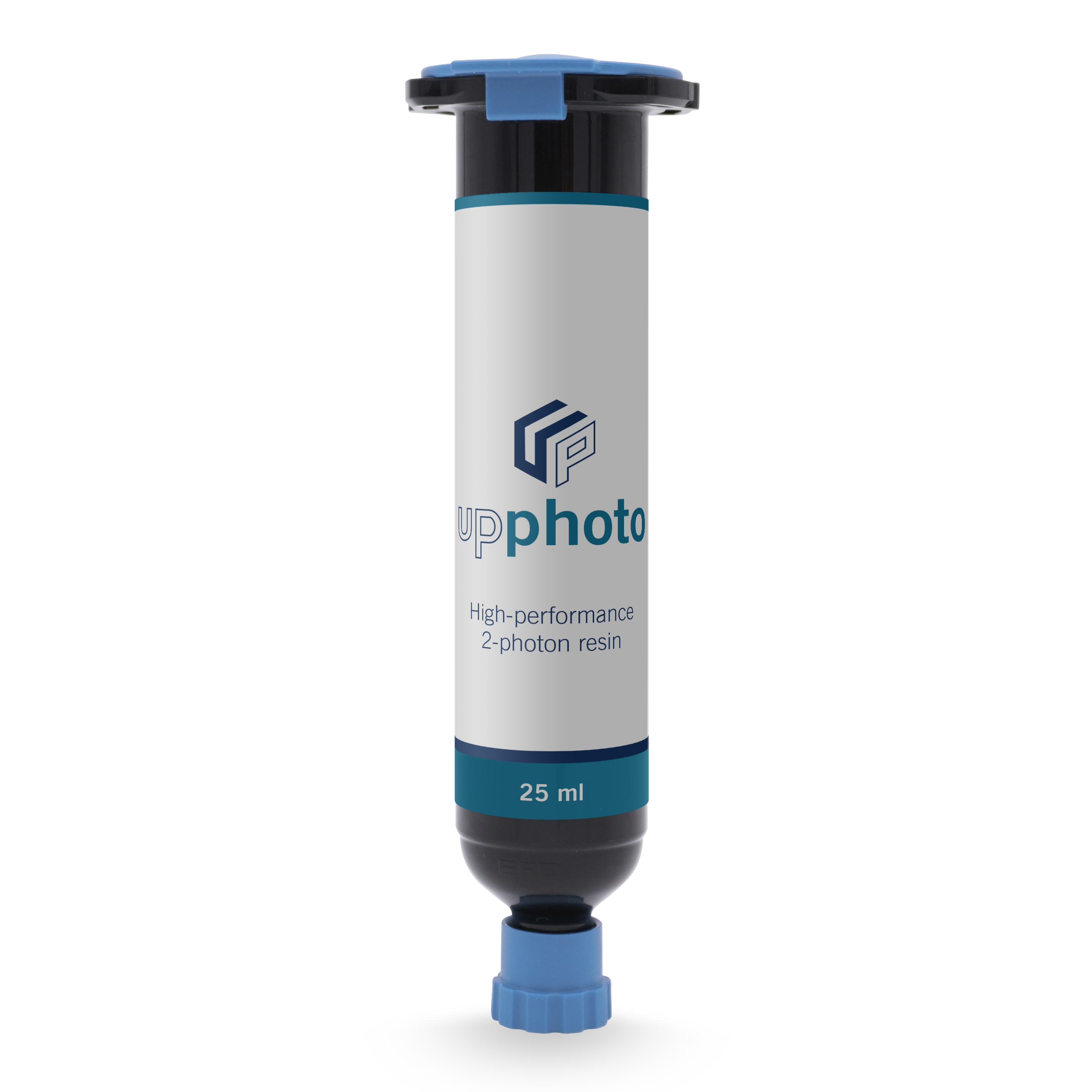
UpPhoto is a high performance 2-photon resin for functional components which are fully cured directly after 3D printing and require no thermal or optical post-processing. The polymerized parts are autoclavable and non-cytotoxic according to EN ISO 10993-5:2009.
Printing parameters
Recommended printing parameters in FINE mode
|
|
FINE UpPhoto
|
|||
|---|---|---|---|---|
|
Objective
|
Line distance
|
Layer slicing
|
Infill speed
|
Infill power
|
|
Zeiss 5x / 0.25
|
1 µm
|
8 µm
|
750 mm/s
|
250 mW
|
|
UPLXAPO10X / 0.4
|
0.5 µm
|
3 µm
|
600 mm/s
|
50 mW
|
|
UAPON20XW340 / 0.7
|
0.3 µm
|
0.9 µm
|
300 mm/s
|
20 mW
|
|
UPLXAPO40XO / 1.4
|
0.2 µm
|
0.5 µm
|
150 mm/s
|
10 mW
|
|
UPLXAPO60XO / 1.42
|
0.15 µm
|
0.5 µm
|
100 mm/s
|
6 mW
|
Recommended printing parameters in COARSE mode
|
|
COARSE UpPhoto
100% coarse width |
|||
|---|---|---|---|---|
|
Objective
|
Line distance
|
Layer slicing
|
Infill speed
|
Infill power
|
|
Zeiss 5x / 0.25*
|
8 µm
|
10 µm
|
750 mm/s
|
280 mW
|
|
UPLXAPO10X / 0.4
|
4.2 µm
|
5 µm
|
600 mm/s
|
100 mW
|
|
UAPON20XW340 / 0.7
|
2.1 µm
|
1.5 µm
|
300 mm/s
|
50 mW
|
|
UPLXAPO40XO / 1.4
|
1.25 µm
|
0.5 µm
|
150 mm/s
|
15 mW
|
|
UPLXAPO60XO / 1.42
|
0.7 µm
|
0.5 µm
|
100 mm/s
|
8 mW
|
* Cannot be printed using the NanoOne 250 system.
These are recommended printing parameters optimized for good resolution at high throughput.
Resolution and throughput are reciprocal. When reducing the layer spacing or hatching the power needs to be reduced accordingly. This can be easily done by an array parameter screening.
Development process
IPA (2-propanol, CAS 67-63-0) is recommended for the development of the printed parts. At least two to three baths for at least 10 min per bath are recommended. Development times and cycles can be adjusted depending on the size and geometry of the actual part. Especially parts with small internal channels need longer development cycles. Since UpPhoto is highly cured after printing, keeping the parts in development for longer will not harm the parts.
IPA– 10 min
IPA– 10 min
IPA– 10 min
Post-processing
Post-processing of the printed parts is not needed. Printed parts are already fully polymerized after the printing process with maximized associated mechanical properties.
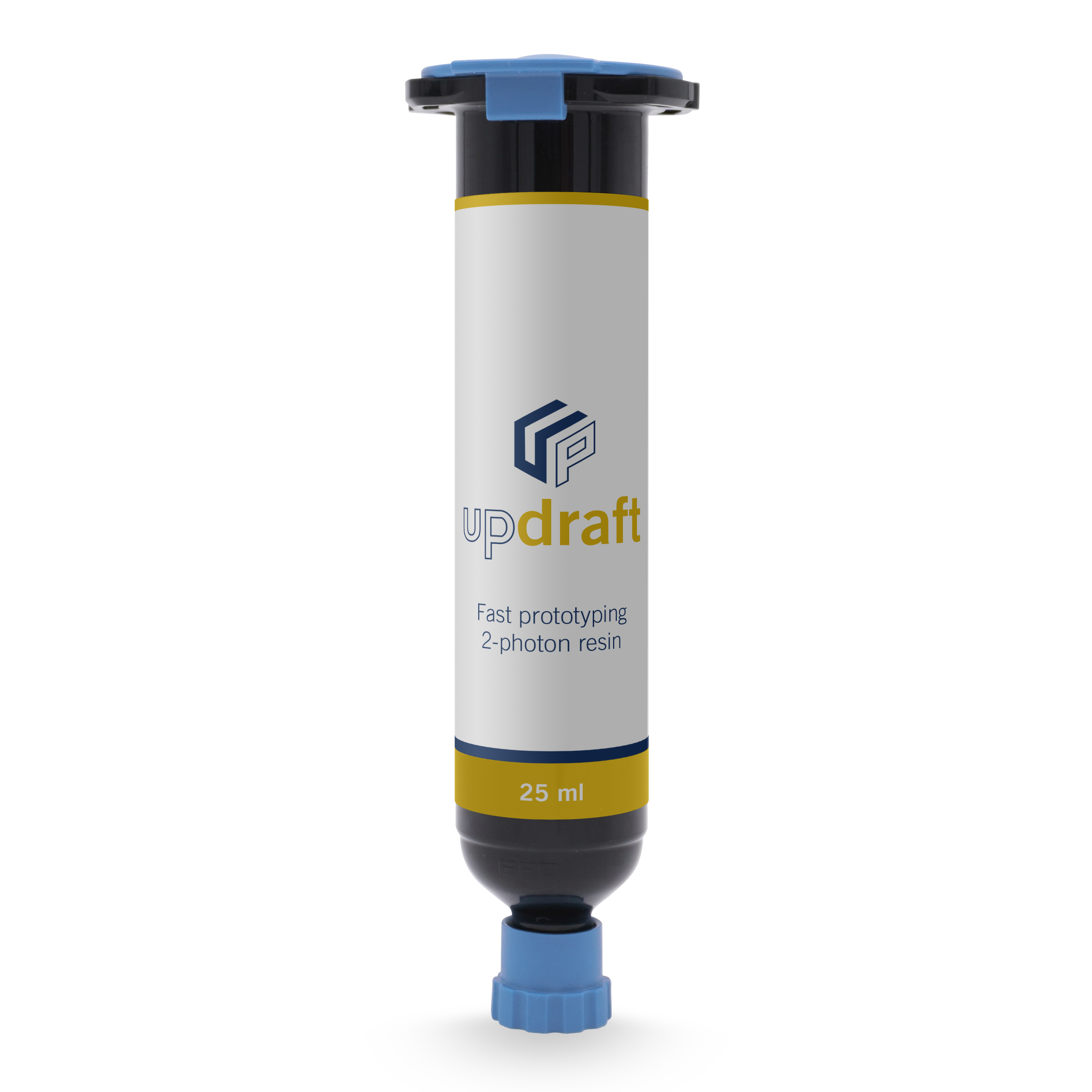
UpDraft
UpDraft is a fast prototyping resin, which is optimized for throughput, it’s ideal for producing the first prototypes. The chemical reactivity of the resin allows increasing the layer spacing and thus enables ultra fast 3D printing of microparts. UpDraft is tolerant to print parameters variations, enabling fast iteration cycles.
Printing parameters
Recommended printing parameters in FINE mode
|
|
FINE UpDraft
|
|||
|---|---|---|---|---|
|
Objective
|
Line distance
|
Layer slicing
|
Infill speed
|
Infill power
|
|
Zeiss 5x / 0.25
|
1 µm
|
8 µm
|
750 mm/s
|
150 mW
|
|
UPLXAPO10X / 0.4
|
0.5 µm
|
5 µm
|
600 mm/s
|
50 mW
|
|
UAPON20XW340 / 0.7
|
0.3 µm
|
1 µm
|
300 mm/s
|
20 mW
|
|
UPLXAPO40XO / 1.4
|
0.15 µm
|
0.45 µm
|
150 mm/s
|
10 mW
|
|
UPLXAPO60XO / 1.42
|
0.15 µm
|
0.5 µm
|
100 mm/s
|
6 mW
|
Recommended printing parameters in COARSE mode
|
|
COARSE UpDraft
100% coarse width |
|||
|---|---|---|---|---|
|
Objective
|
Line distance
|
Layer slicing
|
Infill speed
|
Infill power
|
|
Zeiss 5x / 0.25*
|
8 µm
|
10 µm
|
750 mm/s
|
280 mW
|
|
UPLXAPO10X / 0.4
|
4 µm
|
5 µm
|
600 mm/s
|
80 mW
|
|
UAPON20XW340 / 0.7
|
2 µm
|
1.5 µm
|
300 mm/s
|
50 mW
|
|
UPLXAPO40XO / 1.4
|
1 µm
|
0.5 µm
|
150 mm/s
|
20 mW
|
|
UPLXAPO60XO / 1.42
|
0.8 µm
|
0.5 µm
|
100 mm/s
|
8 mW
|
* Cannot be printed using the NanoOne 250 system.
| Resin refractive index (nD20) | 1.486 |
|---|
These are recommended printing parameters optimized for good resolution at high throughput.
Resolution and throughput are reciprocal. When reducing the layer spacing or hatching the power needs to be reduced accordingly. This can be easily done by an array parameter screening.
Development process
IPA (2-propanol, CAS 67-63-0) is recommended for the development of the printed parts. At least two to three baths for at least 10 min per bath are recommended. Development times and cycles can be adjusted depending on the size and geometry of the actual part. Especially parts with small internal channels need longer development cycles. Since UpPhoto is highly cured after printing, keeping the parts in development for longer will not harm the parts.

IPA– 10 min

IPA– 10 min

IPA– 10 min
Post-processing
Post-processing of the printed parts is not needed. Printed parts are already fully polymerized after the printing process with maximized associated mechanical properties.
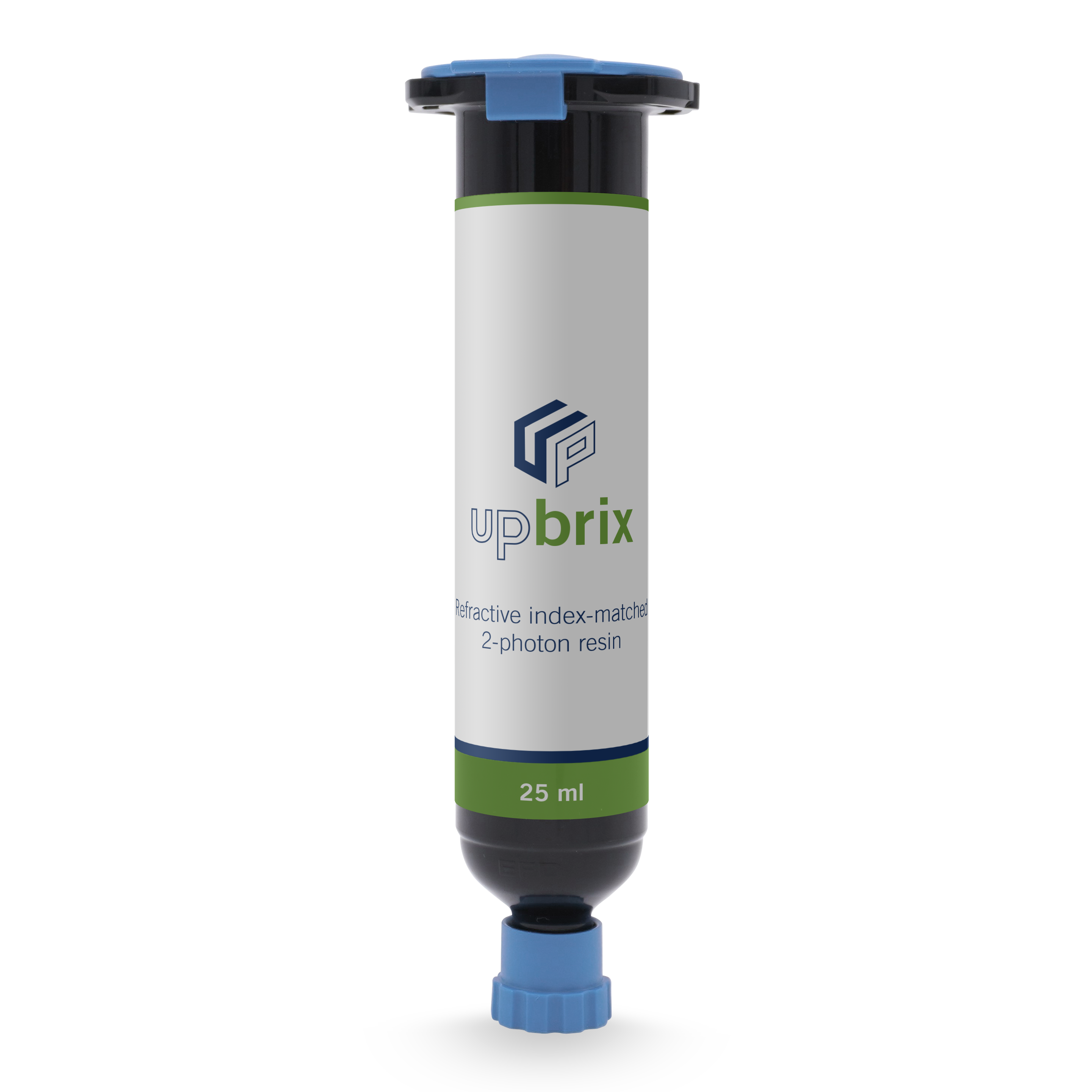
UpBrix
UpBrix is a refractive index-matched 2-photon resin. The refractive index is matched to the immersion oil of high NA objectives. It is used for ultra-high-resolution applications and is ideal for the fabrication of 2.5D patterns as wells as structural details in the micro- and nanometer range.
Printing parameters
Recommended printing parameters in FINE mode
|
|
FINE UpBrix
|
|||
|---|---|---|---|---|
|
Objective
|
Line distance
|
Layer slicing
|
Infill speed
|
Infill poer
|
|
UPLXAPO40XO / 1.4
|
0.2 µm
|
0.25 µm
|
150 mm/s
|
10 mW
|
|
UPLXAPO60XO / 1.42
|
0.15 µm
|
0.2 µm
|
100 mm/s
|
6 mW
|
Recommended printing parameters in COARSE mode
|
|
COARSE UpBrix
100% coarse width |
|||
|---|---|---|---|---|
|
Objective
|
Line distance
|
Layer slicing
|
Infill speed
|
Infill power
|
|
UPLXAPO40XO / 1.4
|
1 µm
|
0.5 µm
|
150 mm/s
|
20 mW
|
|
UPLXAPO60XO / 1.42
|
0.8 µm
|
0.45 µm
|
100 mm/s
|
8 mW
|
* Cannot be printed using the NanoOne 250 system.
| Resin refractive index (nD20) | 1.518 |
|---|
These are recommended printing parameters optimized for good resolution at high throughput.
Resolution and throughput are reciprocal. When reducing the layer spacing or hatching the power needs to be reduced accordingly. This can be easily done by an array parameter screening.
Development process
For development, at least one to two baths in PGMEA (1-methoxy-2-propylacetat, CAS 108-65-6), and a final wash in IPA (2-propanol, CAS 67-63-0) are recommended. Development times and cycles depend on the size and geometry of the actual part and can be adjusted accordingly.
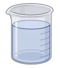
PGMEA – 15 min
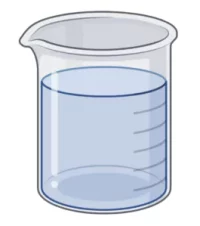
PGMEA – 5 min
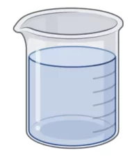
IPA– 2 min
Post-processing
Post-processing of the printed parts is not needed. Printed parts are already fully polymerized after the printing process with maximized associated mechanical properties.
UpOpto
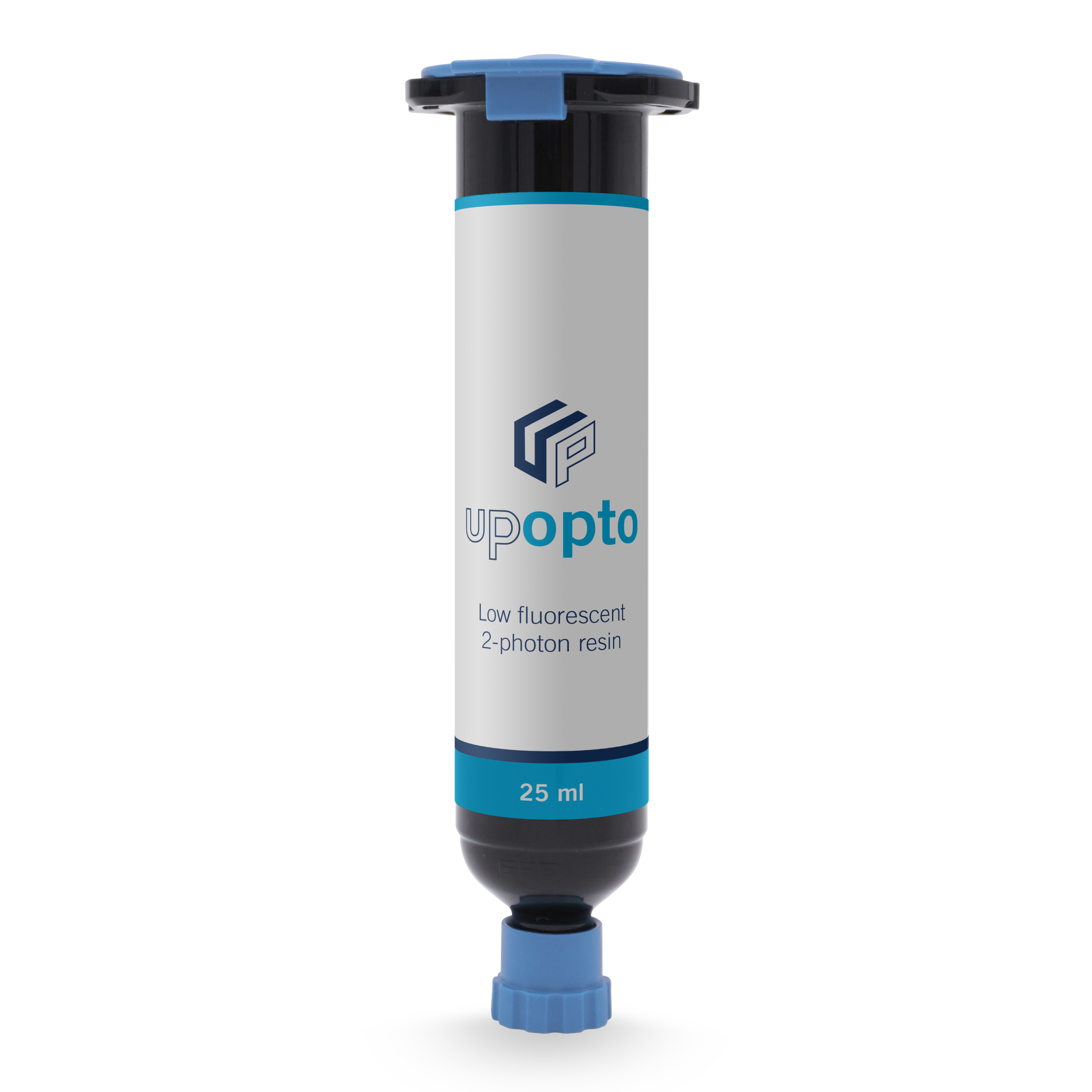
UpOpto is an ultralow-fluorescent 2-photon resin featuring high optical transparency. Unlike standard 2PP resins, it has ultralow autofluorescence and transmission down to the 350nm range. The material is non-cytotoxic, certified according to EN ISO 10993-5:2009. UpOpto obtains its final properties after a UV post-curing step.
Printing parameters
Recommended printing parameters in FINE mode
|
|
FINE UpOpto
|
|||
|---|---|---|---|---|
|
Objective
|
Line distance
|
Layer slicing
|
Infill speed
|
Infill power
|
|
Zeiss 5x / 0.25*
|
-
|
-
|
-
|
-
|
|
UPLXAPO10X / 0.4
|
0.5 µm
|
3.5 µm
|
600 mm/s
|
110 mW
|
|
UAPON20XW340 / 0.7
|
0.3 µm
|
0.5 µm
|
300 mm/s
|
70 mW
|
|
UPLXAPO40XO / 1.4
|
0.2 µm
|
0.5 µm
|
100 mm/s
|
55 mW
|
|
UPLXAPO60XO / 1.42
|
0.2 µm
|
0.25 µm
|
50 mm/s
|
40 mW
|
Recommended printing parameters in COARSE mode
|
|
COARSE UpOpto
75% coarse width |
|||
|---|---|---|---|---|
|
Objective
|
Line distance
|
Layer slicing
|
Infill speed
|
Infill power
|
|
Zeiss 5x / 0.25*
|
-
|
-
|
-
|
-
|
|
UPLXAPO10X / 0.4**
|
3 µm
|
4 µm
|
600 mm/s
|
400 mW
|
|
UAPON20XW340 / 0.7
|
1.5 µm
|
2.5 µm
|
300 mm/s
|
150 mW
|
|
UPLXAPO40XO / 1.4
|
0.75 µm
|
0.5 µm
|
100 mm/s
|
90 mW
|
|
UPLXAPO60XO / 1.42
|
0.5 µm
|
0.45 µm
|
50 mm/s
|
60 mW
|
* UpOpto is not suitable to be printed with Zeiss 5x / 0.25 objective.
** Cannot be printed using the NanoOne 250 system.
| Resin refractive index (nD20) | 1.485 |
|---|
These are recommended printing parameters optimized for good resolution at high throughput.
Resolution and throughput are reciprocal. When reducing the layer spacing or hatching the power needs to be reduced accordingly. This can be easily done by an array parameter screening.
Development process
For development, two sequential baths in PGMEA (1-methoxy-2-propylacetat, CAS 108-65-6), and a final wash in 2-propanol (CAS 67-63-0) are recommended. Development times depend on the size and geometry of the actual part and can be adjusted accordingly. To receive a colorless and low-fluorescent part, development baths should be strictly used for UpOpto only. Check contamination of the bath with any fluorescence dye with black light, before adding UpOpto parts. The material is light sensitive (amber filter recommended).

PGMEA – 15 min

PGMEA – 5 min

IPA– 2 min
Post-processing
UpOpto parts, other than parts printed from UpNano’s fluorescent resins, are not fully cured after printing and require a final UV post curing step. For post-curing, the printed parts after development, can be placed in an appropriate UV chamber (365 nm–405 nm) and exposed for approximately 30–60 minutes.
Printed parts appear yellowish after development. During post-curing, bleaching occurs, and the parts become transparent.
Starting a print job with UpOpto
1. Finding the substrate – material interface
Place the substrate of choice in the stage insert and move the vat filled with UpOpto upwards, until the substrate is in contact with the material (as a starting point use the z- stage position usually used for UPLXAPO10X / 0.4 objective when starting a print job).
2. Adjusting the camera settings
To be able to see the material – substrate interface and camera settings in Think3D software (in particular exposure time and gain) need to be adjusted by using the slide bar. Start with adjusting both to at least ¼ of the slide bar and continue increasing or decreasing both until you have a similar brightness and resolution appearance of the substrate-material interface as when you are using UpPhoto.
3. Positioning the laser spot at the substrate–material interface
Because of the low-flourescent nature of the resin, the current auto-focus mechanism in Think3D is not possible to use. To position the laser spot at the substrate-material interface as accurately as possible, we recommend the following steps:
i. Use the sample camera to focus on a corner of the substrate.
ii. Activate the crosshair function and align the crosshair with the corner of the substrate.
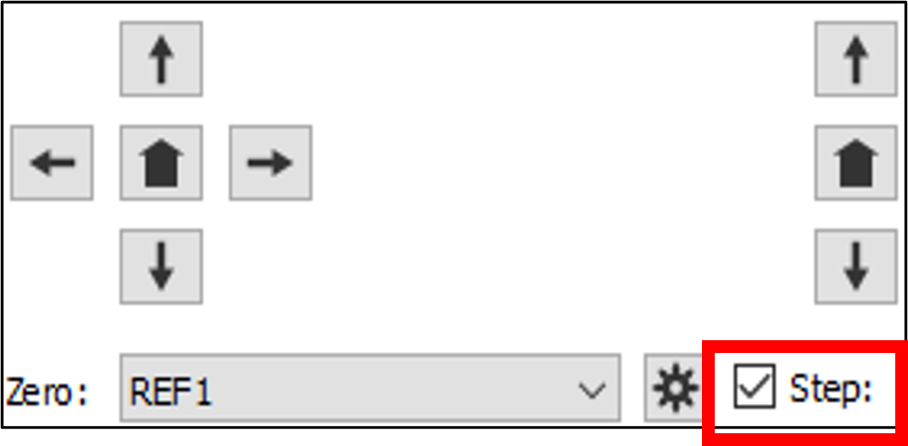
iii. Use the Step function to move to the Center point of the substrate. The step size must be half the substrate width. Please ensure to deselect the step function immediately after each move to avoid the risk of accidental movement in the wrong direction, which could result in the substrate crashing into the bottom of the vat.
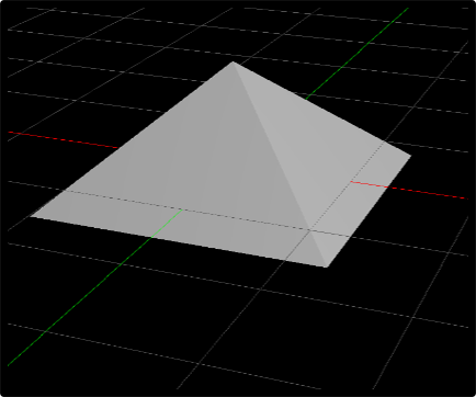
iv. Once positioned at the center of the substrate, save the Center point with Set Point button. Next, turn on the laser, open the pyramid print job for the respective objective and print at the center point.
Example: For the 10x/0.4A objective, the pyramid is set up to be 100 µm high and should have an edge length of 200 µm visible at the base. The actual structure is 240 µm x 240 µm at the base and 120 µm high, but negatively offset by 20 µm into the substrate. This way printing without the attachment on the substrate is avoided.
v. Move back to the saved Center point z-position by double clicking the home button.

vi. Measure the side lengths (enable autosize view for a better view and more precise measurement) in x (distx) and y (disty) direction of the printed pyramid by aligning the crosshair to one corner and moving the crosshair to a corner on the opposite side. The required z-axis movement is calculated using this formula.
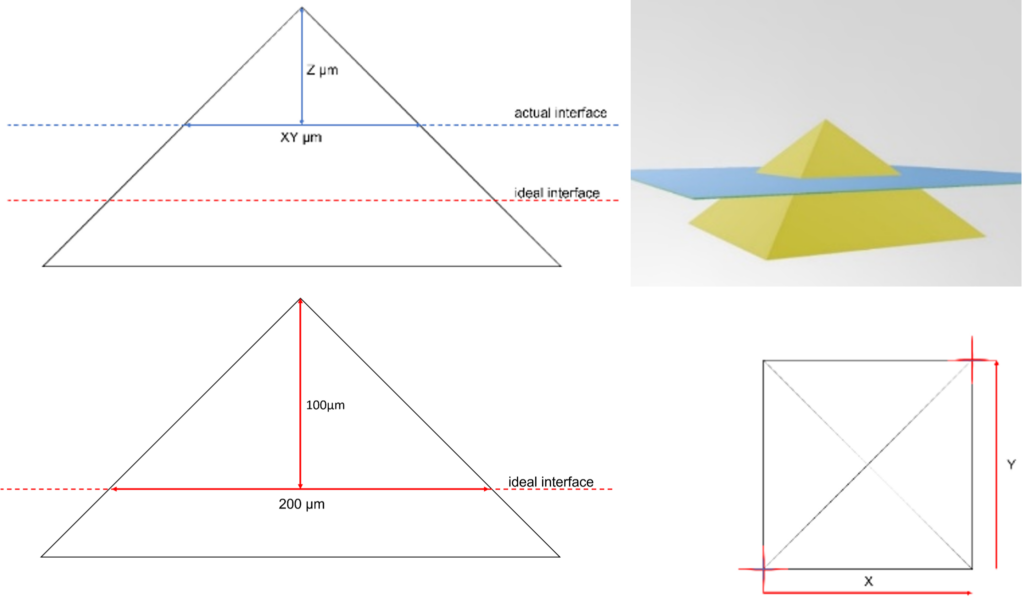
Example: For 10x/0.4A objective, if the pyramid’s footprint is too small it indicates that the interface position is lower than the current z-position and the z-stage must be moved down.
Once the required z-axis movement is calculated, depending on the part size, it can be typed in the Step function and the movement can be executed. Once the movement is finished, overwrite the z-value of the Center point by pressing Set Point and start the print job. For levelling the substrate as precise as possible, a few iterations of this procedure might be necessary.
Downloads
Please click the images below to download the documents.



UpBlack
UpBlack is a low-transmissive 2-photon resin. The visually black and non-transparent resin for 2PP printing is a real masterpiece. The material has light blocking properties in the UV and VIS spectral range. Yet, the material is transparent to NIR and IR radiation, enabling the printing of fine details. The resin is non-cytotoxic, certified according to EN ISO 10993-5:2009.
Printing
For UpBlack, printing with the UPLXAPO 10X/0.4 objective is recommended. For printing the usage of an immersion vat is required. Due to the strong absorption of the material, an auxiliary LED is used for navigation on the substrate. After the LED lamp is successfully mounted, camera settings need to be adjusted accordingly. For more detailed instruction, see below.
Printing parameters
Recommended printing parameters in FINE mode
|
|
FINE UpBlack
|
|||
|---|---|---|---|---|
|
Objective
|
Line distance
|
Layer slicing
|
Infill speed
|
Infill power
|
|
UPLXAPO10X / 0.4
|
0.5 µm
|
3 µm
|
600 mm/s
|
90 mW
|
Recommended printing parameters in COARSE mode
|
|
COARSE UpBlack
75% coarse width |
|||
|---|---|---|---|---|
|
Objective
|
Line distance
|
Layer slicing
|
Infill speed
|
Infill power
|
|
UPLXAPO10X / 0.4*
|
4 µm
|
5 µm
|
600 mm/s
|
180 mW
|
* Cannot be printed using the NanoOne 250 system.
| Resin refractive index (nD20) | 1.489 |
|---|
Development process
For development of UpBlack parts, at least one to two baths in PGMEA (1-methoxy-2-propylacetat, CAS 108-65-6), and a final wash in 2-propanol (CAS 67-63-0) are recommended. Development times depend on the size and geometry of the actual part and can be adjusted accordingly. To avoid staining of other parts, UpBlack should be developed separately from parts printed of other resins.

PGMEA – 15 min

PGMEA – 5 min

IPA– 2 min
Post-processing
Post-processing (UV or thermal curing) of the printed parts is not required. Parts are already sufficiently polymerized after the printing process, if the recommended parameters have been used.
Printing with UpBlack
Introduction
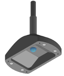
When printing with UpBlack, to find the substrate–material interface and to monitor the start of the print job, the usage of the UpBlack auxiliary LED lamp (Figure 1) is required. Also, an immersion vat needs to be – even when using the 10x objective which would be an AIR immersion objective.
The current version of the UpBlack auxiliary LED lamp, only supports 10×10 mm glass substrates. However, 20×20 mm and 40×40 mm glass substrates can also be used, but due to technical limitations of the lamp, the edges of these larger substrates cannot be seen.
Technical details
The UpBlack auxiliary LED lamp emits green light in the 450-600 nm wavelength range. Due to the high brightness of the light, it is highly advised not to look directly into the light and reflections.
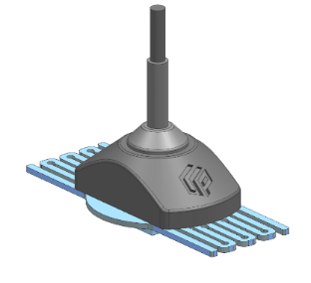
Mounting the lamp
Starting a print job with UpBlack
1. Finding the substrate – material interface
Place the substrate of choice in the stage insert and move the vat filled with UpBlack upwards, until the substrate is in contact with the material (as a starting point use the z- stage position usually used for UPLXAPO10X / 0.4 objective when starting a print job).
2. Adjusting the camera settings
To be able to see the material – substrate interface and camera settings in Think3D software (in particular exposure time and gain) need to be adjusted by using the slide bar. Start with adjusting both to at least ¼ of the slide bar and continue increasing or decreasing both until you have a similar brightness and resolution appearance of the substrate – material interface as when you are using UpPhoto.
Due to the nature of Beer-Lambert’s law, the transmission through the resin decreases as the path length of the light increases since the material vat is moving downwards with the progressing print. Therefore, the UpBlack auxiliary LED lamp only allows to accurately find the substrate–material interface and monitor the initial print of the first few layers. With increasing part height, the light will fade, and monitoring becomes impossible.
3. Positioning the laser spot at the substrate–material interface
Because of the low-flourescent nature of the resin, it’s not possible to use the current auto-focus mechanism in Think3D. To position the laser spot at the substrate-material interface as accurately as possible, we recommend the following steps:
i. Use the sample camera to focus on a corner of the substrate.
ii. Activate the crosshair function and align the crosshair with the corner of the substrate.

iii. Use the Step function to move to the Center point of the substrate. The step size must be half the substrate width. Please ensure to deselect the step function immediately after each move to avoid the risk of accidental movement in the wrong direction, which could result in the substrate crashing into the bottom of the vat.

iv. Once positioned at the center of the substrate, save the Center point with Set Point button. Next, turn on the laser, open the pyramid print job for the respective objective and print at the center point.
Example: For the 10x/0.4A objective, the pyramid is set up to be 100 µm high and should have an edge length of 200 µm visible at the base. The actual structure is 240 µm x 240 µm at the base and 120 µm high, but negatively offset by 20 µm into the substrate. This way printing without the attachment on the substrate is avoided.
v. Move back to the saved Center point z-position by double clicking the home button.

vi. Measure the side lengths (enable autosize view for a better view and more precise measurement) in x (distx) and y (disty) direction of the printed pyramid by aligning the crosshair to one corner and moving the crosshair to a corner on the opposite side. The required z-axis movement is calculated using this formula.

Example: For 10x/0.4A objective, if the pyramid’s footprint is too small it indicates that the interface position is lower than the current z-position and the z-stage must be moved down.
Once the required z-axis movement is calculated, depending on the part size, it can be typed in the Step function and the movement can be executed. Once the movement is finished, overwrite the z-value of the Center point by pressing Set Point and start the print job. For levelling the substrate as precise as possible, a few iterations of this procedure might be necessary.
Downloads
Please click the images below to download the documents.

UpFlow
UpFlow is a low-viscosity and low-fluorescent 2-photon resin. The optical transparency and low viscosity make the resin ideal for printing microfluidic channels smaller than 50 µm. In addition, the resin exhibits low autofluorescence and is certified as non-cytotoxic according to EN ISO 10993-5:2009. UpFlow obtains its final properties after a UV post-curing step.
Printing parameters
Recommended printing parameters in FINE mode
|
|
FINE UpFlow
|
|||
|---|---|---|---|---|
|
Objective
|
Line distance
|
Layer slicing
|
Infill speed
|
Infill power
|
|
Zeiss 5x / 0.25*
|
-
|
-
|
-
|
-
|
|
UPLXAPO10X / 0.4**
|
0.5 µm
|
5 µm
|
600 mm/s
|
220 mW
|
|
UAPON20XW340 / 0.7
|
0.3 µm
|
1 µm
|
300 mm/s
|
100 mW
|
|
UPLXAPO40XO / 1.4
|
0.2 µm
|
0.5 µm
|
150 mm/s
|
70 mW
|
Recommended printing parameters in COARSE mode
|
|
COARSE UpFlow
100% coarse width |
|||
|---|---|---|---|---|
|
Objective
|
Line distance
|
Layer slicing
|
Infill speed
|
Infill power
|
|
Zeiss 5x / 0.25*
|
-
|
-
|
-
|
-
|
|
UPLXAPO10X / 0.4**
|
4 µm
|
5 µm
|
600 mm/s
|
400 mW
|
|
UAPON20XW340 / 0.7
|
2.5 µm
|
1.5 µm
|
300 mm/s
|
150 mW
|
|
UPLXAPO40XO / 1.4
|
1.05 µm
|
0.5 µm
|
150 mm/s
|
90 mW
|
* UpFlow is not suitable to be printed with Zeiss 5x / 0.25 objective.
** Cannot be printed using the NanoOne 250 system.
| Resin refractive index (nD20) | 1.480 |
|---|
These are recommended printing parameters optimized for good resolution at high throughput.
Resolution and throughput are reciprocal. When reducing the layer spacing or hatching, it might be necessary to adjust the power accordingly. The relation of these two parameters and the optimal parameter set for your print can easily be determined by printing an array parameter screening.
Development process
For development, at least one to two baths in PGMEA (1-methoxy-2-propylacetat, CAS 108-65-6), and a final wash in 2-propanol (CAS 67-63-0) are recommended. Development times depend on the size and geometry of the actual part and can be adjusted accordingly. For parts with undercuts or fine channels it is advisable to increase the number of PGMEA baths. To receive a colorless and low-fluorescent part, development baths should be strictly used for UpFlow only. UpFlow parts should always be developed separately from colored and fluorescing resins.

PGMEA – 15 min

PGMEA – 5 min

IPA– 2 min
Post-processing
For post-curing, cleaned parts can be placed in an appropriate UV chamber (365–405 nm) and exposed for approx. 30 minutes depending on the geometry and size of the printed parts.
Printed parts are colorless after development. During post-curing, a slight yellowing can occur.
UpThermo
UpThermo is a high-temperature 2-photon resin. In cooperation with Cubicure, a resin with an exceptionally high heat deflection temperature HDT-B of greater than 300°C was developed. Paired with high mechanical stiffness, it is ideal for static high temperature applications. The resin is non-cytotoxic, certified according to EN ISO 10993-5:2009.
Material preparation
Printing with UpThermo requires the use of a heatable vat, as components of the material tend to crystallize at room temperature. When heating the material to 60°C these crystals dissolve. Note that depending on the storage temperature and age of the material, crystallization can be pronounced to a varying extent.
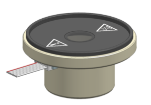
First, the material is dispensed in the heatable vat, and the temperature setting is enabled in the Think3D software and set to 60°C. The temperature should be kept constant during the course of a print. Please, take care not to overfill the vat as the material volume will expand when heating up. Substrates can be preheated in an oven or by using a heat gun at low temperature. This way, bubble formation can be avoided.
Printing parameters
Recommended printing parameters in FINE mode
|
|
FINE UpThermo
|
|||
|---|---|---|---|---|
|
Objective
|
dxy
|
dz
|
Speed
|
Power
|
|
Zeiss 5x / 0.25
|
1 µm
|
8 µm
|
750 mm/s
|
140 mW
|
|
UPLXAPO10X / 0.4
|
0.5 µm
|
5 µm
|
600 mm/s
|
40 mW
|
Recommended printing parameters in COARSE mode
|
|
COARSE UpThermo
100% course width |
|||
|---|---|---|---|---|
|
Objective
|
dxy
|
dz
|
Speed
|
Power
|
|
Zeiss 5x / 0.25*
|
8 µm
|
10 µm
|
750 mm/s
|
300 mW
|
|
UPLXAPO10X / 0.4
|
4 µm
|
5 µm
|
600 mm/s
|
100 mW
|
* Cannot be printed using the NanoOne 250 system.
| Resin refractive index (nD20) | 1.514 |
|---|
Development process
For the development of the printed parts, we recommend using a staining trough or beaker, and dibasic ester (CAS 95481-62-2) as developer. Development times and cycles can be adjusted depending on the size and geometry of the actual part. We recommend at least one to two baths of dibasic ester and a finishing step in which the part is submersed in IPA (2-propanol, CAS 67-63-0).
Dibasic Ester – 15 min
Dibasic Ester – 5 min
IPA– 2 min
Post-processing
UpThermo parts require thermal post-curing to reach their full mechanical properties. We recommend treating them in a programmable oven using the following settings:
- Start temperature: 25°C
- Heating rate: 3 K min-1
- End temperature: 200°C
- Dwell time at 200°C: 60 min
- Passive cooling: < 80°C
UpSol
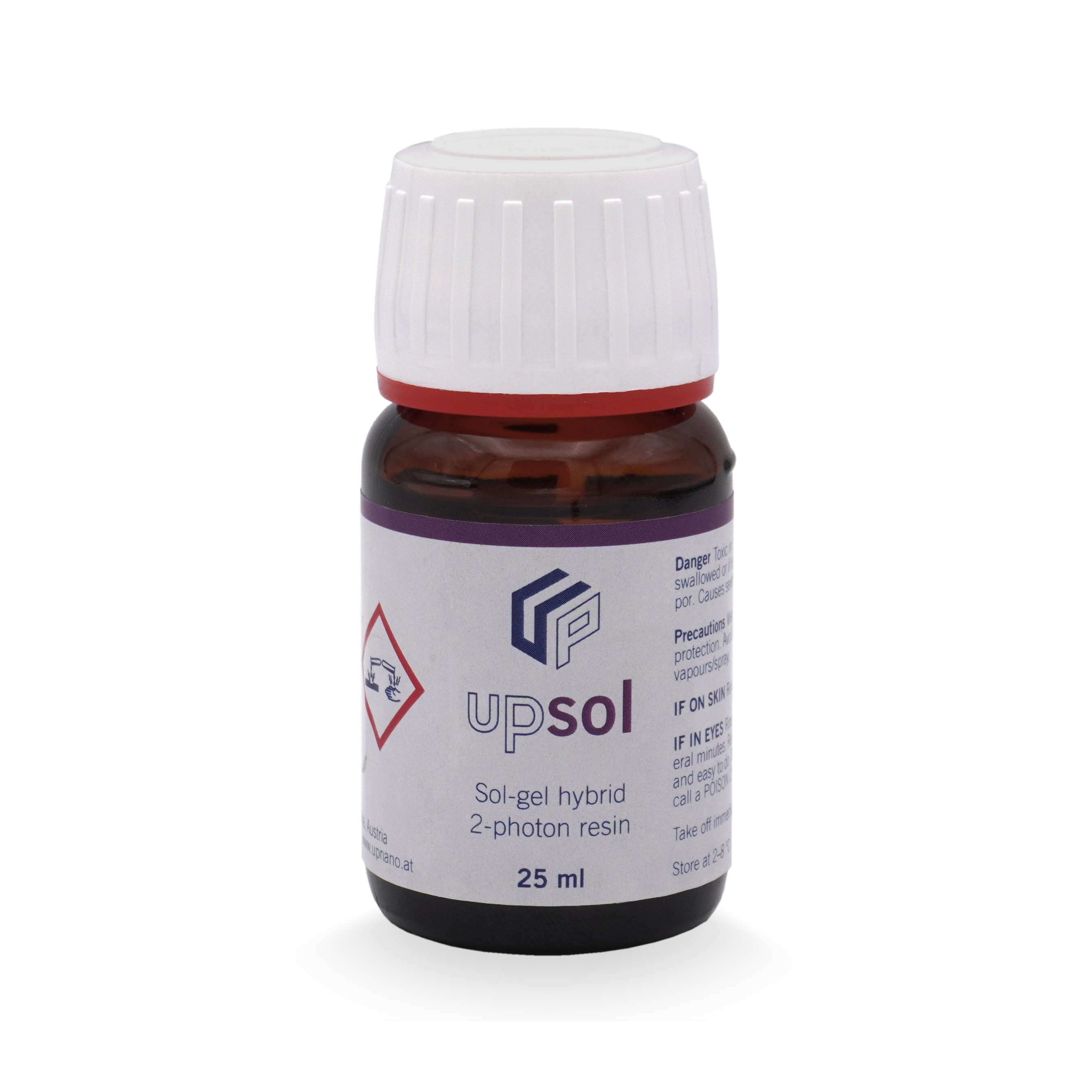
UpSol is a sol-gel hybrid 2-photon resin. The negative thin-film resin can be applied to the intended substrate by spin-coating or drop-casting. During printing, the resin is gel-like and therefore allows the production of complex structures with overhangs and undercuts. Besides 2.5D and 3D microstructures, free-floating elements can also be printed.
Substrate preparation
The desired amount of UpSol needs to be drop-casted on the substrate. Then, the substrate should be dried on a hotplate at 60 °C for 30 min. Time and temperature of the drying step are recommendations and can be adjusted according to the amount of UpSol being used. Due to evaporation of solvent, the layer height decreases.
Printing parameters
Recommended printing parameters in FINE mode
|
|
FINE UpSol
|
|||
|---|---|---|---|---|
|
Objective
|
dxy
|
dz
|
Speed
|
Power
|
|
Zeiss 5x / 0.25*
|
-
|
-
|
-
|
-
|
|
UPLXAPO10X / 0.4
|
0.5 µm
|
4 µm
|
600 mm/s
|
70 mW
|
|
UAPON20XW340 / 0.7
|
0.3 µm
|
1.5 µm
|
300 mm/s
|
20 mW
|
|
UPLXAPO40XO / 1.4
|
0.15 µm
|
0.25 µm
|
150 mm/s
|
10 mW
|
|
UPLXAPO60XO / 1.42
|
0.15 µm
|
0.2 µm
|
100 mm/s
|
6 mW
|
Recommended printing parameters in COARSE mode
|
|
COARSE UpSol
(100% course width) |
|||
|---|---|---|---|---|
|
Objective
|
dxy
|
dz
|
Speed
|
Power
|
|
Zeiss 5x / 0.25*
|
-
|
-
|
-
|
-
|
|
UPLXAPO10X / 0.4
|
3 µm
|
4 µm
|
600 mm/s
|
150 mW
|
|
UAPON20XW340 / 0.7
|
2.5 µm
|
1.5 µm
|
300 mm/s
|
50 mW
|
|
UPLXAPO40XO / 1.4
|
1.25 µm
|
0.5 µm
|
150 mm/s
|
15 mW
|
|
UPLXAPO60XO / 1.42
|
0.8 µm
|
0.5 µm
|
100 mm/s
|
8 mW
|
* UpSol is not suitable to be printed with Zeiss 5x / 0.25 objective.
| Resin refractive index (nD20) | 1.510 |
|---|
These are recommended printing parameters optimized for good resolution at high throughput.
Resolution and throughput are reciprocal. When reducing the layer spacing or hatching the power might need to be reduced accordingly. This can be easily done by an array parameter screening.
Development process
After printing, the substrate is submersed in 1-propanol (CAS 71-23-8) until the excess UpSol is removed. Thereafter a 1 min wash in fresh 1-propanol is recommended. Development times do depend on the size and geometry of the actual part and need to be adjusted accordingly.
1-propanol – 15 min
1-propanol – 1 min

UpQuartz
UpQuartz is a 2-photon silica slurry. It is a nanocomposite slurry for manufacturing fused silica (SiO2) parts using 2-photon polymerization, developed in cooperation with Glassomer. Printed green parts are converted into fused silica by thermal debinding and sintering. After high-temperature treatment, the 2PP-processed parts exhibit the characteristic properties of fused silica glass.
Process scheme
UpQuartz is a composite resin consisting of silica nanoparticles and an organic resin that serves as polymeric binder. The binder is thermally removed after printing by heating the green part up to 600°C in the debinding step. The resulting brown part consists of silica nano particles, which are fused together in the sintering step at 1300°C.

Figure 1: Process scheme of UpQuartz. The printed part (green part) is thermally debound to the brown part at 600°C and subsequently sintered at 1300°C to fused silica.
Design considerations
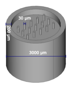
For geometries with vertical, circular holes, the slicing mode should be set to voxel mode and the voxel height needs to be adjusted to, e.g., 60 µm using the 5x objective and 30 µm using the 10x / NA 0.4 objective depending on the target geometry (see Figure 3).
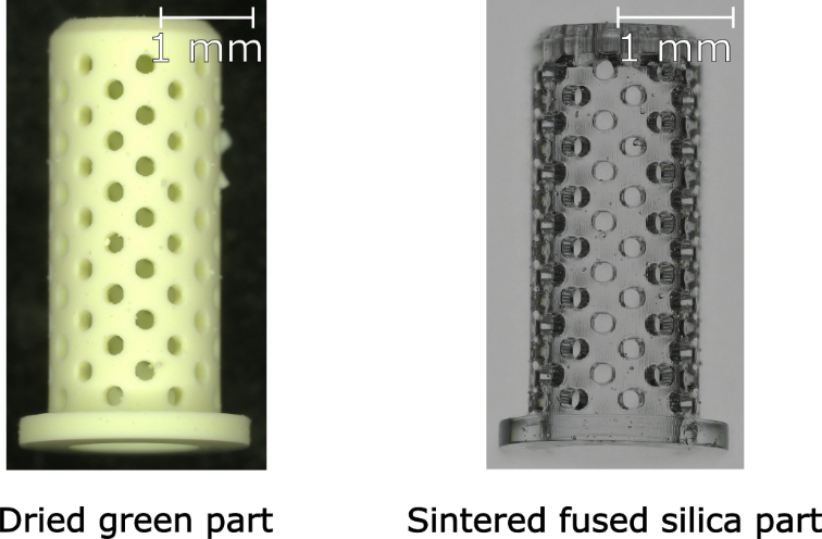
Figure 3: Representative images of a dried green part and the respective fused silica part after thermal debinding and sintering.
Geometries with embedded channels are difficult to develop because the developer breaks the stable dispersion of silica nanoparticles within the monomer matrix. Small and long channels tend to clog due to the precipitation of the nanoparticles within the channel and cannot be washed free fully. Figure 4 displays an example of a developable and a not developable embedded channel structure.

Figure 4: Schematic of embedded channel structures. The left image shows a 2 mm long channel with a diameter of 175 µm (not developable) and the right image a 1 mm long channel (developable).
Consider shrinkage
During the thermal post-processing steps, the part will shrink isotropically in size. Thus, the parts must be scaled by a factor of 1.329 in xyz direction in Think3D to compensate for the isotropic shrinkage. UpQuartz is suited for printed geometries with up to 3 mm bulk feature thickness.
General notes and printing parameters
The 100 µm objective spacer is necessary for the 10x objective to raise the focal point further from the vat. This increases the distance between the substrate and the vat during the printing process. Omitting this step can lead to critical failure of the print job.
We recommend turning off the HEPA fan (HEPA Fan Power Closed) or covering it while printing with UpQuartz. This will prevent the material from gelling and prolong the stability of it in the vat.
We recommend using only designated vats for UpQuartz to avoid cross contamination of the silica particles with any other materials.
|
Printing parameters
|
|||
|---|---|---|---|
|
In-fill mode
|
COARSE
|
FINE
|
|
|
Objective
|
5x
|
10x*
|
10x*
|
|
Line distance
|
8 μm
|
4 μm
|
4 μm
|
|
Layer height
|
12.5 μm
|
5 μm
|
4 μm
|
|
Power
|
200 mW
|
150 mW
|
75 mW
|
|
Infill speed
|
400 mm/s
|
600 mm/s
|
75 mm/s
|
* Use 100 µm objective spacer.
These printing parameters were tested for certain print job geometries. The final printing parameters can vary depending on the geometry of the target part.
Required equipment for post-processing of UpQuartz
Debinding process
Furnace: An ashing furnace (air atmosphere) is required for the thermal debinding process.
For example: Ashing Furnace AAF (Carbolite/Gero, UK)
Aluminum oxide plates (porous): We recommend using porous aluminum oxide plates to place the part on. These plates support the exit of the reaction gases from the UpQuartz part. ( e.g., Keralpor99, Kerafol, Germany)
Proper ventilation and removal of the furnace exhaust needs to be ensured at all times.
Sintering process
The sintering step can be performed either in air atmosphere or in vacuum. For a higher glass quality, we recommend a vacuum tube oven.
Furnace
Sintering furnace in air: Austromat 664 (Dekema, Germany)
Vacuum tube oven: STF16/450 (Carbolite/Gero, UK) at a pressure of 1 ×10 2 mbar
Aluminum oxide plates (dense): Place debounded samples on dense, low surface roughness aluminum oxide plates to minimize friction during shrinkage, reducing the risk of critical failure in UpQuartz parts. (e.g., Alsint 99,7, Buntenkoetter, Germany)
Post-processing of UpQuartz – additional information
Development process
The printed object (green part) is developed in PGMEA (1-methoxy-2-propylacetat, CAS 108-65-6) using a magnetic stirrer at ~150–200 rpm. Development times depend on the size and geometry of the target design. Filigree objects and high aspect ratio geometries should be developed hanging upside down (e.g., by using a 100 mL screw top bottle or a beaker). The container needs to be filled with the developer so that the print is fully immersed. To reduce the evaporation of the developer, a beaker should be placed over the container (see Figure 5).
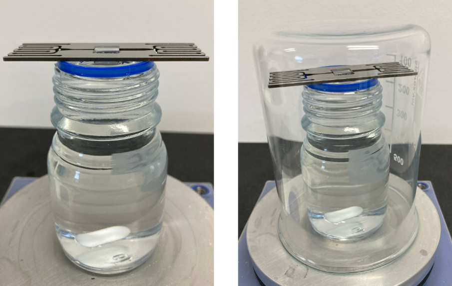
Figure 5: Exemplary set-up for upside down development of filigree and/or high aspect ratio geometries
Bulky objects and low aspect ratio geometries can be developed with a closed lid or by using a watch glass over a beaker to avoid evaporation (see Figure 6).
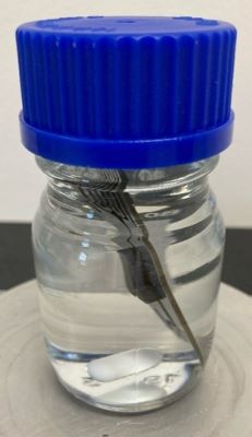
Figure 6: Exemplary developing set-up for bulky and low aspect ratio geometries
We recommend using at least two separate developing baths, where the last bath consists of fresh PGMEA. To ensure that the green part is fully developed, we also recommend checking if the developer bath shows fluorescence using an UV-lamp. If the developer shows fluorescence, we recommend using an additional developer bath with fresh PGMEA. UpQuartz parts should be developed separately to other 2PP materials to avoid contamination, since UpQuartz contains silica nanoparticles. We recommend not to touch the prints as long as they are wet with the developer to avoid defects. In this state, the prints resemble a soft organogel.
After the print is fully developed, it needs to dry at room temperature. We recommend drying the developed parts for at least 4 hours, depending on the size and geometry. Filigree objects and high aspect ratio geometries should be dried hanging upside down (see Figure 7). After drying the print for 30 minutes hanging upside down, it should be rotated upright to avoid detachment. The upside-down drying time depends on the size and geometry of the target part. During the drying process, the color of the print changes from a green appearance to greenish white (see Figure 3).
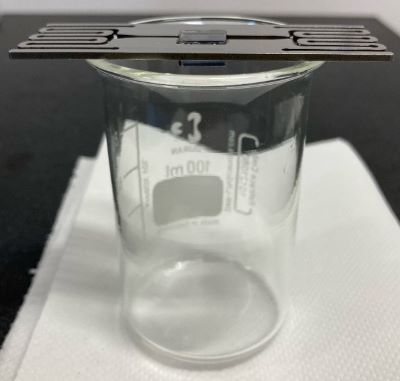
Figure 7: Exemplary set-up for upside-down drying filigree and/or high aspect ratio geometries
Speeding up the drying process by using compressed air or nitrogen is not recommended as the part is quite soft and fragile and fast drying can lead to cracks. We recommend detaching the prints after drying for the thermal post-processing. The dried parts need to be handled with care due to their brittle nature.
Note: During the drying process, the green parts already shrink by ~10% (this is already included in the total shrinkage factor). This shrinkage can already lead to a weak attachment between the green parts and the substrate, which results in an easier detachment of the green parts for the subsequent post-processing steps. Therefore, the dried substrates need to be handled with care to avoid unwanted detachment.
Thermal Debinding
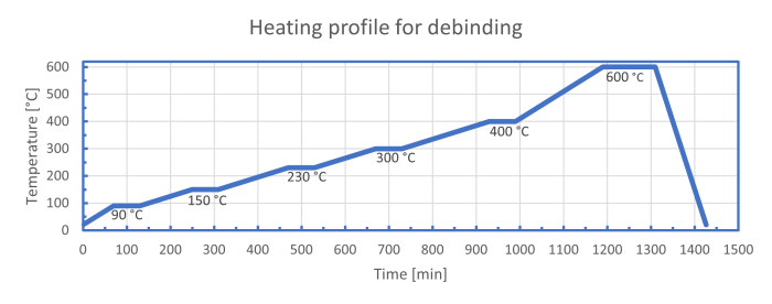
Printed objects undergo initial debinding in an ashing oven to eliminate the organic binder matrix, necessitating air atmosphere. Ensure samples are at room temperature before placing them in the oven and starting the debinding process. Green parts must not be placed in a preheated furnace! The green parts need to be allowed to cool down slowly within the oven according to the heating profile. For safety and to prevent crystallization, handle samples with latex or nitrile gloves, avoiding direct contact with skin.
Small and filigree objects can be debinded and sintered in the sintering oven in one step by combining both heating profiles. However, be aware that the debinding step requires an air atmosphere.
Table 1: Heating profile for debinding parts from UpQuartz
|
Target temperature
|
Heating rate
|
Dwell time
|
|||
|---|---|---|---|---|---|
|
90 °C
|
1 °C/min
|
60 min
|
|||
|
150 °C
|
0.5 °C/min
|
60 min
|
|||
|
230 °C
|
0.5 °C/min
|
60 min
|
|||
|
300 °C
|
0.5 °C/min
|
60 min
|
|||
|
400 °C
|
0.5 °C/min
|
60 min
|
|||
|
600 °C
|
1 °C/min
|
120 min
|
|||
|
20 °C
|
5 °C/min
|
-
|
|||
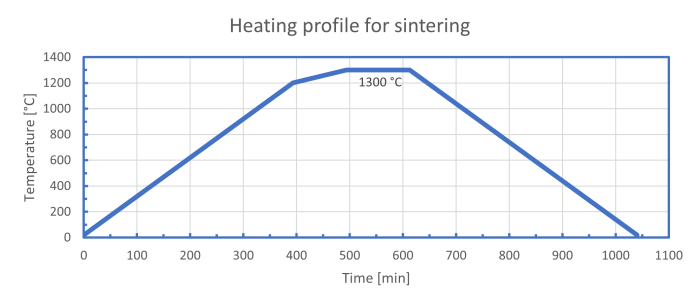
Sintering
The debound parts are sintered to fully dense fused silica at 1300°C. The debound brown parts have a chalk-like nature and are very sensitive to mechanical force. Be careful whilst transferring the samples from one furnace to another and only touch the debound parts using latex or nitrile gloves.
The debound parts are sintered to fully dense fused silica at 1300°C. The debound brown parts have a chalk-like nature and are very sensitive to mechanical force. Be careful whilst transferring the samples from one furnace to another and only touch the debound parts using latex or nitrile gloves.
Always detach the printed objects from standard glass substrates before placing them in the sintering furnace! They consist of borosilica glass and will melt below 1300°C!
Table 2: Heating profile for sintering parts printed from UpQuartz
|
Target temperature
|
Heating rate
|
Dwell time
|
|||
|---|---|---|---|---|---|
|
1200 °C
|
3 °C/min
|
-
|
|||
|
1300 °C
|
1 °C/min
|
120 min
|
|||
|
20 °C
|
3 °C/min
|
-
|
|||
Total sintering time: 620 min (cooling time not included)
